iMXceet UL-2/ULL S Boards and Kits
Models
| Name | Kit Number | Board Number | Description |
|---|---|---|---|
| iMXceet UL-2 S | 50099 023 | 40099 111 | Demoboard with i.MX6UL-SoM |
| iMXceet UL-2 S 43 | 50099 018 | 40099 111 | Demoboard with i.MX6UL-SoM, 4.3" Display and cap. Touch |
| iMXceet UL-2 S 43 RS485 | 50099 025 | 40099 111 | Demoboard with i.MX6UL-SoM, 4.3" Display and cap. Touch and CAN (instead of RS485) |
| iMXceet UL-2 S 50 | 50099 022 | 40099 111 | Demoboard with i.MX6UL-SoM, 5" Display and cap. Touch |
| iMXceet UL-2 S 70 | 50099 020 | 40099 111 | Demoboard with i.MX6UL-SoM, 7" Display and cap. Touch |
| iMXceet UL-2 S 70 (DisplayLine) | 50099 029 | 40099 111 | DisplayLine (without frame) with i.MX6UL-SoM, 7" Display and cap. Touch |
| iMXceet UL-2 S 70 (DisplayLine) | 50099 031 | 40099 111 | DisplayLine (with frame) with i.MX6UL-SoM, 7" Display and cap. Touch |
| iMXceet ULL S 50 | 50099 042 | 40099 147 | Demoboard with i.MX6ULL-SoM, 5" Display and cap. Touch |
| iMXceet ULL S 50 (DisplayLine) | 50099 027 | 40099 147 | DisplayLine (without frame) with i.MX6ULL-SoM, 5" Display and cap. Touch |
| KBox A-330 MX6 ULL | 50575 004 | 40099 148 | Kontron KBox with i.MX6ULL-SoM, without Display |
Info
Boards are only boards without housing and peripherals.
Kits are complete eval/demo-kits that might include a housing,
peripherals such as displays and accessories.
PCB History 40099 111, 40099 147 (deprecated / is no longer produced!)
| Revision | PCB Number | Description/Changes |
|---|---|---|
| R000 | 1 951 1461 | |
| R001 | 1 952 1461 | |
| R002 | 1 953 1461 |
PCB History 40099 148 (currently used/produced PCB version)
| Revision | PCB Number | Description/Changes |
|---|---|---|
| R000 | 1 951 1670 | |
| R001 | 1 952 1670 | Bugfix DIOs |
Components/Features
This board consists of two main units:
- The SoM, which is the more complex component including processor and DDR3 RAM.
- The baseboard including additional storage and containing all necessary connectors.
The SoM is soldered to the baseboard.
SoM
- CPU: i.MX6 UltraLite (max. 528 MHz), i.MX6 ULL (max. 792 MHz)
- 256/512 MB DDR3 RAM
- 1 MB SPI NOR Flash
- 256/512 MB QSPI NAND Flash
- 1x Ethernet PHY
Baseboard
- 4GB eMMC
- Micro SD-Card Slot
- 2x USB Host
- 1x USB OTG
- 1x Ethernet PHY
- 2x Ethernet Connector (RJ45)
- RS232
- RS485 (or CAN)
- 3x Debug Leds
- RGB-Display Interface
- 2x Digital IOs
- 2x Analog Inputs
- PWM Buzzer
- 8KB nvSRAM (SPI)
Important Note: The SOM-Baseboard has been released in two major releases. The first release (1 95x 1461) is equipped with white connectors and the second release (1 95x 1670) is equipped with black connectors.
The first release is not produced anymore and therefore will be called deprecated in this documentation. Furthermore the hw-description of the interfaces/connectors below contains also both releases.
Serial Interfaces
Also see BSP / Using the Hardware / Serial Interfaces.
You need an additional adapter to translate the 3.3V-UART signals (provided on the Mini-SUB port) to USB.
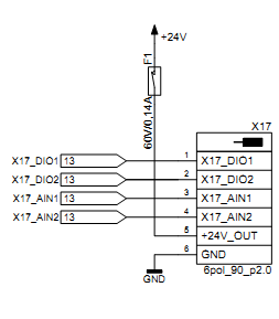
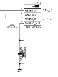
1 95x 1461 (deprecated)
| i.MX6 | Used as | Accessible via | Connector |
|---|---|---|---|
| uart1 | RS232 | /dev/ttymxc0 |
X16 (3pol) |
| uart2 | - | - | - |
| uart3 | RS232 | /dev/ttymxc2 |
X8 (Extension) |
| uart4 | Debug | /dev/ttymxc3 |
X11 |
| uart5 FlexCAN |
RS485 CAN |
/dev/ttymxc1 SocketCAN:can0 |
X18 (4pol) |
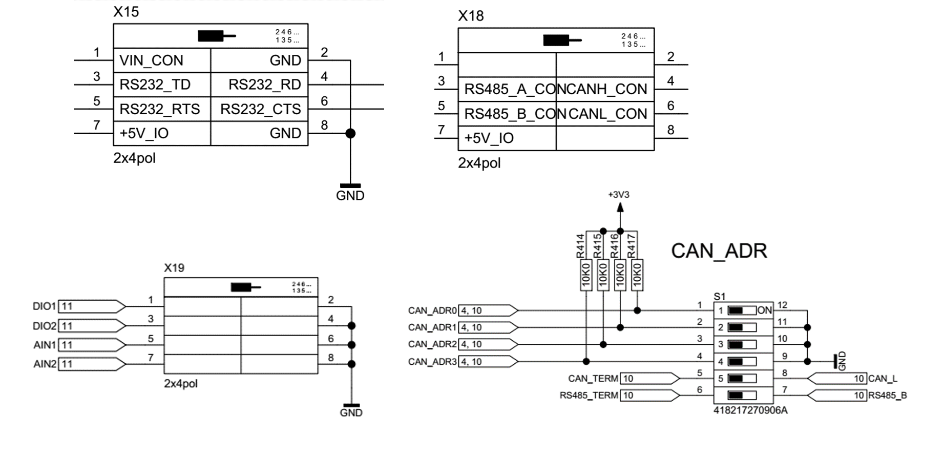
1 95x 1470
| i.MX6 | Used as | Accessible via | Connector |
|---|---|---|---|
| uart1 | RS232 | /dev/ttymxc0 |
X15 (8pol) |
| uart2 | RS485 | /dev/ttymxc1 |
X18 (8pol) |
| uart3 | - | - | - |
| uart4 | Debug | /dev/ttymxc3 |
X11 |
| uart5 | - | - | - |
CAN Interface
The current release of the baseboard allows you to use both the CAN Interface and the RS485 Interface simultanously. In the first release this was not possible. The CAN Interface is located at the same connector as the RS485 Interface - which is connector X18.
On the Software side please refer to official (Kernel)-Documentation about "SocketCAN" which is the protocol used by the Linux Kernel (https://www.kernel.org/doc/Documentation/networking/can.txt).
PWM-Beeper
The PWM-Beeper can be controlled via the userspace tool beep:
beep -e /dev/input/event1
by sending a BEL character to the console:
echo -e "\a" > /dev/tty0
or by using
ioctl("/dev/input/event1",KIOCSOUND,<tone>)
Warning
There is a hardware bug in revision 0 of the baseboard (1 951 1461), that might cause system crashes and errors while using the PWM-Beeper.
Digital IOs
Two digital inputs/outputs (either or) are available. If used as output the state can be read back from the associating input.
Furthermore two analog inputs are available.
The table below shows number and function of available GPIOs. You can access them via the GPIO Sys-interface (deprecated) /sys/class/gpio or by using libgpiod -> BSP / Using the Hardware / GPIOs.
| Name | direction | GPIO_NUMBER | Linux Access | Connector (1 95x 1461) | Connector (1 95x 1670) |
|---|---|---|---|---|---|
| DIO1 | input/output | GPIO5_IO05 | gpioget gpiochip4 5 / gpioset gpiochip4 5=1 |
X17_DIO1 | X19_DIO1 |
| din1 | input | GPIO5_IO04 | gpioget gpiochip4 4 |
- | - |
| DIO2 | input/output | GPIO5_IO01 | gpioget gpiochip4 1 / gpioset gpiochip4 1=1 |
X17_DIO2 | X19_DIO2 |
| din2 | input | GPIO5_IO00 | gpioget gpiochip4 0 |
- | - |
Analog Inputs
There are two analog inputs available on the board, connected to the internal ADC of the i.MX6UL
| Name | Accessible via | Connector (1 95x 1461) | Connector (1 95x 1670) |
|---|---|---|---|
| AIN1 | /sys/bus/iio/devices/iio\:device0/in_voltage3_raw |
X17_AIN1 | X19_AIN1 |
| AIN2 | /sys/bus/iio/devices/iio\:device0/in_voltage8_raw |
X17_AIN2 | X19_AIN2 |
Voltage calculation in mV from the raw value:
U = in_voltageX_raw * (25,8 / 3,3) mV
DIP switch S1 (only available at PCB Number 1 95x 1670)
The switch called CAN_ADR has 6 contacts. Two of them are responsible for the termination of RS485 and CAN Bus signals. It may be necessary to enable the termination to eliminate distortion of the bus signal.
The other four contacts are inputs and can be accessed like regular GPIOs. (BSP / Using the Hardware / GPIOs)
| Name | signal number | function | GPIO |
|---|---|---|---|
| CAN_ADR0 | 1 | Input | gpiochip0 24 |
| CAN_ADR1 | 2 | Input | gpiochip0 25 |
| CAN_ADR2 | 3 | Input | gpiochip0 26 |
| CAN_ADR3 | 4 | Input | gpiochip0 27 |
| CAN_TERM | 5 | CAN bus termination | - |
| RS485_TERM | 6 | RS485 bus termination | - |
LEDs
3 Debug Leds are available and can be controlled with the /sys/class/leds
directory
nvSRAM
The 8KB nvSRAM can be accessed from the file
/sys/class/spi_master/spi0/spi0.0/eeprom
Display Interfaces
RGB Family Connector
The displays of the devices described in chapter "Models" are connected via the RGB24 interface on the 40-pin connector (X13). The touch lines for the touch controller are pinned separately via X5. The interface can be connected directly to the standard Kontron display without the need of an adapter.
RGB Custom Connector
The board is additionally equiped with a 50-pin RGB connector (X12). In this case, the touch controller pins are included. With this interface customer-specific displays can be connected via a convenient display adapter (attached to the display).
Ethernet
| Name | Connector (1 95x 1461) | Connector (1 95x 1670) | Linux device |
|---|---|---|---|
| Ethernet 1 | X2 | X16 | eth1 |
| Ethernet 2 | X6 | X6 | eth0 |
Appendix
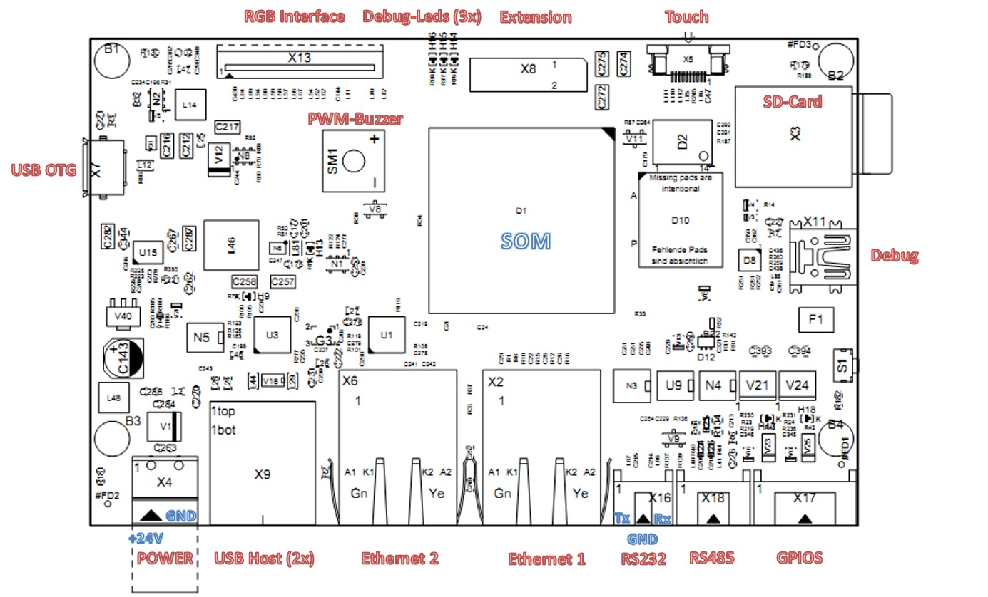
Board Layout (40099 148 / 195x 1670)
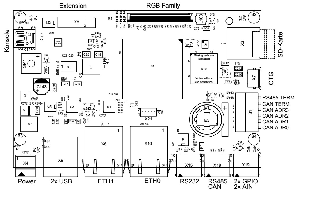
Connector Pinouts (40099 148 / 195x 1670)
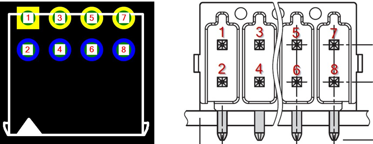
RS232, RS485/CAN, Digital IOs, analog inputs, DIP Switch
Pinout
Board Layout (40099 147 / 195x 1461, deprecated!)
Connector Pinouts (40099 147 / 195x 1461, deprecated!)