BL i.MX8MM (N801x S)
Board Layout and Connectors
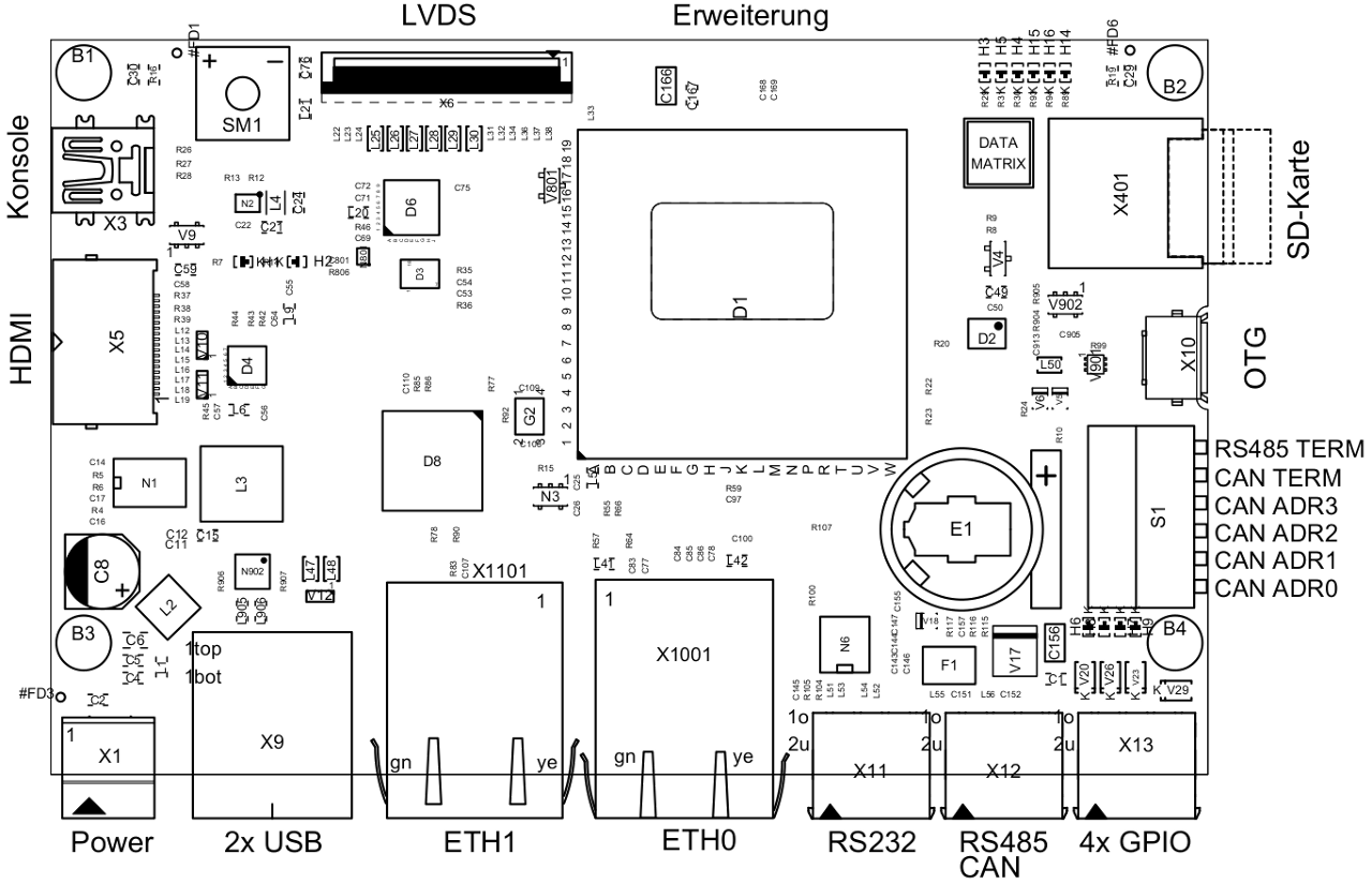
IOs
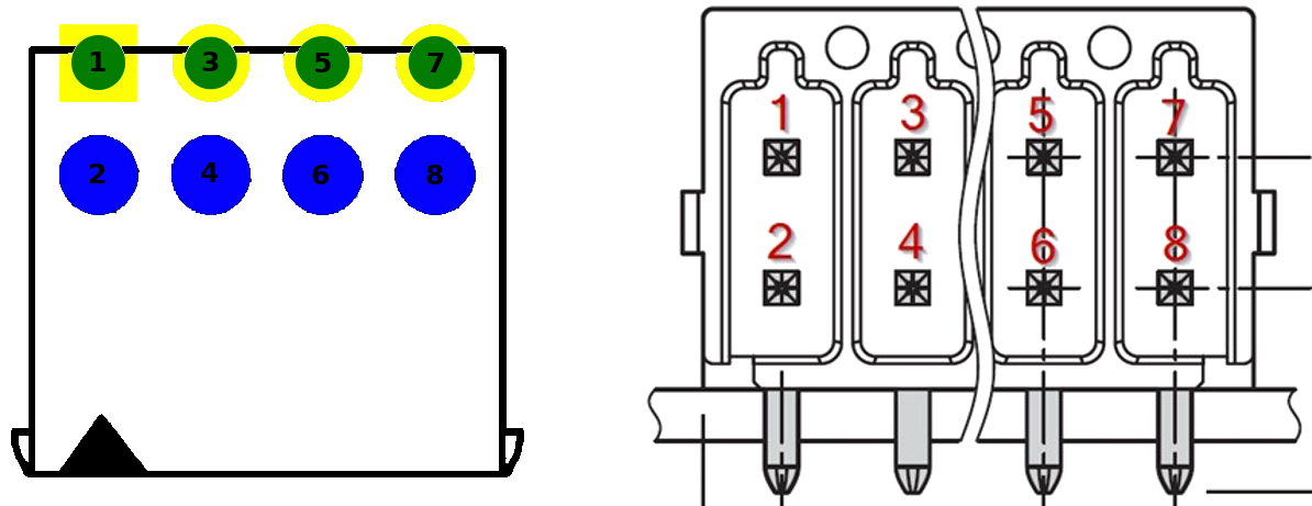
Four digital inputs/outputs (either or) are available.
The table below shows number and function of available DIOs and their associated GPIOs.
The input/output voltage is coupled to the power supply voltage (normally 24 volts).
| DIO Name | Direction | GPIO Name | GPIO Device | GPIO Offset | Connector |
|---|---|---|---|---|---|
| DIO1 | output | GPIO1_IO03 |
gpiochip0 | 3 | X13 - Pin 1 |
| DIO1 | input | GPIO1_IO06 |
gpiochip0 | 6 | X13 - Pin 1 |
| DIO2 | output | GPIO1_IO07 |
gpiochip0 | 7 | X13 - Pin 3 |
| DIO2 | input | GPIO1_IO08 |
gpiochip0 | 8 | X13 - Pin 3 |
| DIO3 | output | GPIO1_IO09 |
gpiochip0 | 9 | X13 - Pin 5 |
| DIO3 | input | GPIO1_IO10 |
gpiochip0 | 10 | X13 - Pin 5 |
| DIO4 | output | GPIO1_IO011 |
gpiochip0 | 11 | X13 - Pin 7 |
| DIO4 | input | GPIO5_IO02 |
gpiochip4 | 2 | X13 - Pin 7 |
For an example on how to use or work with the DIOs see section "Using the System" for more information.
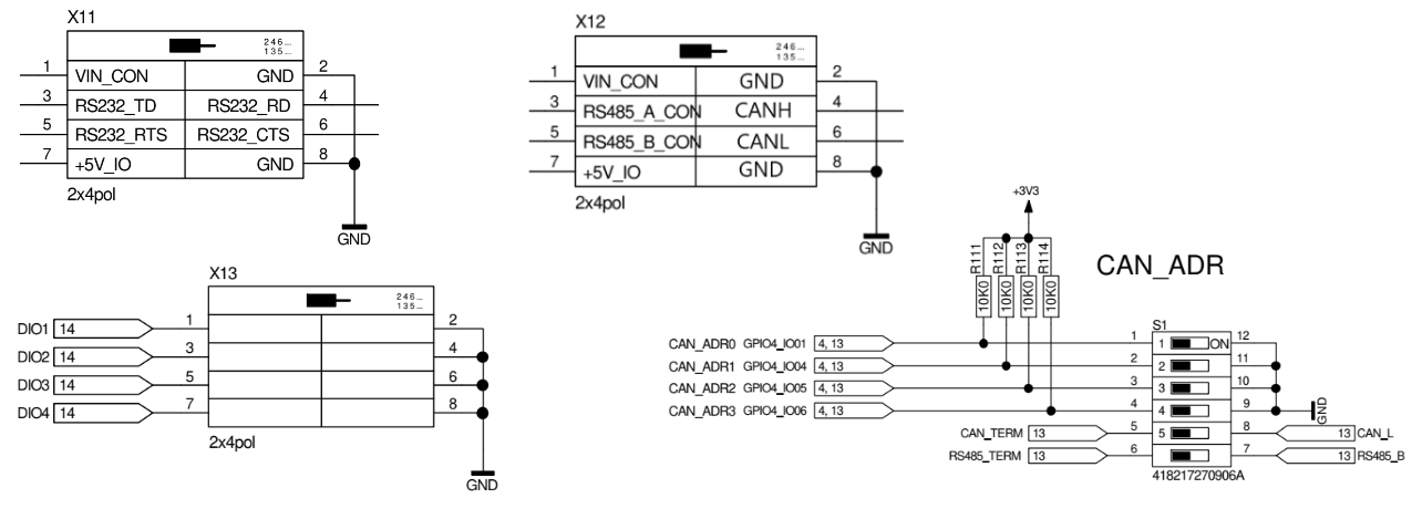
Serial Devices
Below you will find an overview which serial device has which name in the OS and belongs to which UART device of the iMX8 CPU.
| UART | Type | Accessible via | Connector |
|---|---|---|---|
| UART 1 | RS232 | /dev/ttymxc0 |
X11 |
| UART 2 | RS485 | /dev/ttymxc1 |
X12 |
| UART 3 | UART/TTL (Debug UART) | /dev/ttymxc2 |
X3 (USB Mini-B) |
For an example on how to use the serial devices see section "Using the System" for more information.
CAN-Bus Interface
The BL i.MX8MM (N801x S) has one CAN-Bus interface. The device is present after boot, but is not enabled by default.
| Name | Accessible via | Connector |
|---|---|---|
| CAN | can0 |
X12 |
For an example on how to use the CAN-Bus see section "Using the System" for more information.