Description for STM32 SOM MP157 devices (rev00)
Identification
| Name | Device number | Components | Identification | Description |
|---|---|---|---|---|
| DK STM32 SOM MP157 | 50099044 rev00 | board: pcb: som: |
40099 131 1 951 1825 40099 167 |
Demo-Kit with STM32MP157A 5" Display and capacitive Touch |
| DK STM32 SOM MP157 | 50099045 rev00 | board: pcb: som: |
40099 131 1 951 1825 40099 167 |
Demo-Kit with STM32MP157A, without Display |
| BL STM32 SOM MP157 | board: pcb: som: |
40099 131 1 951 1825 40099 167 |
Baseboard with STM32MP157A, without Display |
Boards
are only boards without housing and peripherals. Different devices may be based on the same
board.
PCB
The PCB number can be found on the PCB for identification
Demo-Kits
are complete Demo-Kits for a quick start with the product. It often contains connectors,
power plugs, housing and display based on a specific board and SoM.
- For a quick start with these kits see the Quickstart document.
- For connector interfaces and board layout see appendix
Overview of components and features
This board consists of two main units. The SoM which is the more complex component including processor and DDR3-RAM. The second component is actually a baseboard including additional storage and containing all necessary connectors.
The SoM is soldered to the baseboard.
SOM t1000 (40099 167)
- STM32MP157A SOC (2xCortex-A7@650MHz, 1xCortex-M4@200MHz)
- 512 MB DDR3 RAM
- 2 MB QSPI NOR flash
- 512 MB QSPI NAND flash
- 1x Ethernet PHY (100MBit/s)
- 1x I2C GPIO Expander
Baseboard s (40099 131)
- 4GB eMMC
- Micro SD card slot
- 2 x USB host
- 1 x USB OTG
- 1 x USB Ethernet (100 MBit/s)
- 2 x Ethernet Connector (RJ45)
- 1 x RS232
- 1 x RS485 or CAN
- 3 x Debug LEDs
- 2 x Digital IO (GPIO expander)
- 2 x Analog IN
- 1 x PWM beeper
- 1 x Audio out
- Display Interfaces: RGB or DSI
Display and Touch (only display variant)
- 5 inch display with 800x480 resolution
- capacitive multitouch
Software support
These devices are supported by the kontron yocto BSP
| Name | shortname | devicetree file | CubeMX configuration | housing | Description |
|---|---|---|---|---|---|
| DK STM32 SOM MP157 | t1000-s | stm32mp-t1000-s.dts | t1000-s.ioc | without display | |
| DK STM32 SOM MP157 | t1000-s-50 | stm32mp-t1000-s-50.dts | t1000-s.ioc | -50 | |
| BL STM32 SOM MP157 | t1000-s | stm32mp-t1000-s.dts | t1000-s.ioc |
Important
The housing variable in u-boot has to be set to select the correct kit configuration for the
board. See u-boot bootloader for more info.
Notice
The build repository base URL is https://git.kontron-electronics.de/stm32mp. It is recommended
to use the init-env script to checkout and populate all yocto layers and to setup
the yocto environment for this device. See
initializing the yocto build environment
for more information
Yocto configurations
The dedicated software configurations for these Demo-Kits
| build repository | build-stm32mp |
| branches | thud |
| machine | stm32mp-t1000-s-multi |
| init-env command | . init-env -t thud build-stm32mp |
| EULA accept variable | ACCEPT_EULA_stm32mp-t1000-s-multi = "1" |
| distros dedicated for these kits | ktn |
| images dedicated for these kits | image-ktn, image-ktn-qt |
| available boot devices | mmc0 (SD-card), mmc1 (eMMC), ubifs0 (QSPI NAND), pxe (Ethernet1) |
| latest prebuild binaries | https://files.kontron-electronics.de/stm32mp |
Licence information
This product contains software components which are licensed as free respectively open-source software under the GNU General Public License, versions 2 or 3, or the GNU Lesser General Public License, versions 2.1 or 3 or any other open-source licence. Everyone can get the source code of this software components from us by download or by storage medium within three years after the delivery of the product or as long as we offer spare parts or support for the product.
To get the source code on a data storage medium (CD-ROM, DVD, USB drive), please send a request to our customer support at the following address
Kontron Electronics GmbH
Max-Planck-Strasse 6
72636 Frickenhausen
Deutschland

Web: www.kontron-electronics.de
E-Mail: support@kontron-electronics.de
Including the statement of the following product data:
- Product name and product number
- Date of delivery
We also require a fee of EUR 10,- for the costs of preparation of the medium and shipping to be transferred.
Preventive it should be mentioned here that using the right of installing own versions of the open-source software components, which is guaranteed in the licence contract, will expire all certifications and warranties of the product. The operation of the manipulated product will happen on one's own authority.
If you want to download the source code covered by open-source licenses for this product use these URLs:
- For getting binaries, license texts and source code:
https://files.kontron-electronics.de/stm32mp
Look for the appropriate BSP version in this directory or in the archive subdirectory. - For instructions how to build the software:
https://docs.kontron-electronics.de/stm32mp/build-stm32mp
Known issues and limitations
- It is not possible to set the device into the 'Engineering Mode' (M4 debugging without linux running)
- This board provides very limited peripherals for using with M4
- DSI interface is not tested
Description of board components
The following sections describe the hardware components and, if available their interface to to linux os.
Power supply
The power supply is located on X4. The nominal supply voltage is 24V. The average current for the board with display is lower than 200mA.
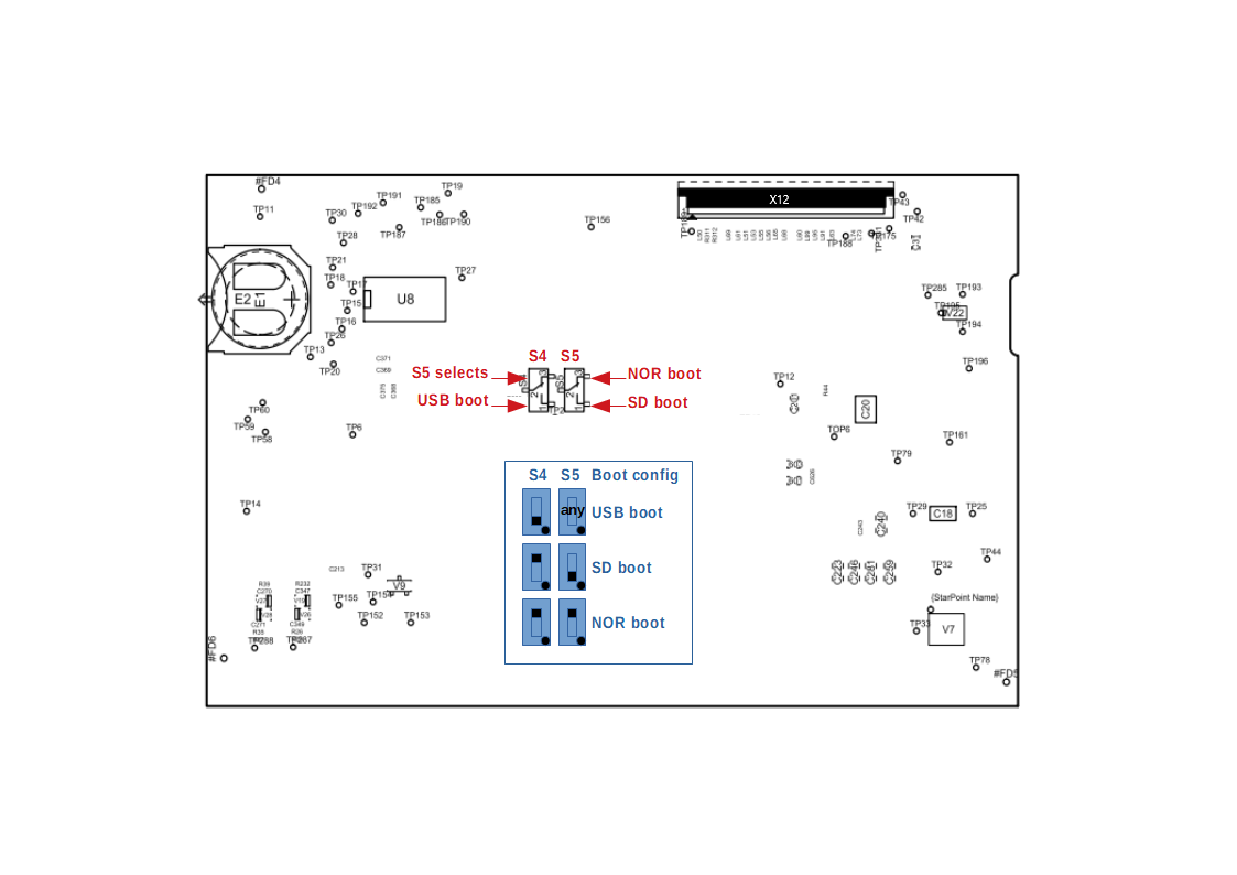
Boot switches
The boot source can be selected by boot switches on the bottom side of the baseboard. For devices with display you have to disassemble the baseboard to be able to change the boot switches. See Appendix to locate the boot switches on your board.
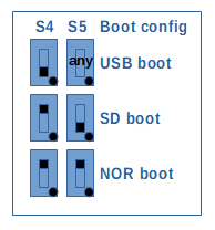
Some remarks to the boot modes:
- As long as the STM32MP1 SOC has no USB connection in USB boot mode, LED1 blinks fast.
- The boards are delivered with SD boot setting.
For these Demo-Kits a boot configuration is written in OTP memory:
BOOT_CONFIG3 = 0x22000000
This means the boot priority are as follos:
| Boot switch setting | BOOT0/1/2 pins on SoM | boot source search sequence |
|---|---|---|
| USB boot | tbd. | USB OTG port waits for CubeProgrammer to send data |
| SD boot | tbd. | SD-card, NOR boot, USB boot |
| NOR boot | tbd. | SD-card, NOR boot, USB boot |
As a conclusion, the setting of SD/NOR boot switch doesn't matter! Only USB boot switch is useful if the device should be started with CubeProgrammer.
See ST Wiki for documentation of boot fuses settings.
Serial Interfaces
Also see Using the hardware.
| STM32MP1 | Used as | Linux access | Connector | Usage |
|---|---|---|---|---|
| uart4 | console | /dev/ttySTM0 |
X11 (MiniUSB) | |
| usart2 | RS485 | /dev/ttySTM1 |
X18 (4pol) | Multipexed with CAN interface |
| usart6 | RS232 | /dev/ttySTM2 |
X16 (3pol) | Reserved for M4 demo program |
How to configure RS485/CAN mode for X18 can be found in Board Layout
Info
You need an additional adapter to translate the 3.3V console UART signals (provided on the Mini-USB port) to USB.
CAN Interfaces
Also see Using the hardware.
| STM32MP1 | Used as | Linux access | Connector | Usage |
|---|---|---|---|---|
| can1 | CAN | SocketCAN:can0 |
X18 (4pol) | Multipexed with RS485 interface. |
How to configure RS485/CAN mode for X18 can be found in Board Layout
Ethernet
Also see Using the hardware.
| Name | Connector | Linux device | Remark |
|---|---|---|---|
| Ethernet 1 | X2 | eth0 | Native SOC interface |
| Ethernet 2 | X6 | eth1 | USB ethernet, not available in u-boot bootloader |
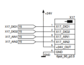
Digital IOs
Also see Using the hardware.
Two digital inputs/outputs (either or) are available. If used as output the state can be read back from the associating input.
The table below shows number and function of available GPIOs. You can access them via the standard
GPIO sysfs interface /sys/class/gpio or by libgpiod (commands gpio*).
| Name | direction | GPIO number (sysfs) |
Accessible via (libgpiod) |
Connector |
|---|---|---|---|---|
| dout1 | output | 507 | gpiochip8.3 |
X17_DIO1 |
| din1 | input | 506 | gpiochip8.2 |
X17_DIO1 |
| dout2 | output | 505 | gpiochip8.1 |
X17_DIO2 |
| din2 | input | 504 | gpiochip8.0 |
X17_DIO2 |
Analog inputs
There are two analog inputs available on the board, connected to the internal ADC
| Name | Accessible via | Connector |
|---|---|---|
| AIN1 | /sys/bus/iio/devices/iio\:device0/in_voltage5_raw |
X17_AIN1 |
| AIN2 | /sys/bus/iio/devices/iio\:device0/in_voltage16_raw |
X17_AIN2 |
For voltage calculation in mV from the raw value see STMicroelectronics Wiki
The scaling formula for the board is:
Uconnector = Uadc * 11
For simplicity there is a adcread script to read adc values which observes all offsets, and
scaling factors. To read out channel 5 on device adc 0 call:
> adcread 0 5
ADC0.5: 16 mV
LEDs
There are 3 debug LEDs available and can be controlled by linux user space or are used by M4 demo program
| Name | Interface | Accessible via | Used as |
|---|---|---|---|
| LED1 | SOC PORTA 13 | M4 demo | M4 demo LED |
| LED2 | SOC PORTA 14 | /sys/class/leds/LED2 |
|
| LED3 | I2C GPIO exander | /sys/class/leds/LED3 |
heartbeat |
Hint
LED1 (PORT A13) is also used to indicate USB boot mode. When STM32MP1 waits for USB connection, LED1 blinks fast.
I2C busses
On this board there are two i2c busses used:
| Name | Accessible via | Used by |
|---|---|---|
| I2C2 | i2c-1 | GPIO SOM, Touch |
| I2C4 | i2c-2 | AUDIO, DSI |
Important
i2c-1 interface is internally used for GPIO port expander TCA6408A on SoM at address 0x20
Devices on i2c-1
| Adresse | Location | Komponente |
|---|---|---|
| 0x20 | SOM | GPIO port expander TCA6408A |
| 0x14 | Housing | Goodix touch |
Devices on i2c-2
| Adresse | Location | Komponente |
|---|---|---|
| 0x1a | Board | Audio WM8510 |
USB host
Also see Using the hardware.
Two USB 2.0 host interfaces are available on connector X9.
USB OTG
Also see Using the hardware.
One USB OTG port is available on connector X7. This USB OTG port is required for USB boot mode.
Audio
Also see Using the hardware.
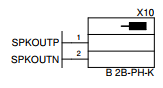
A speaker can be plugged in X10
Display Interfaces
Also see Using the hardware.
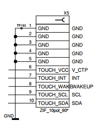
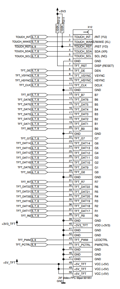
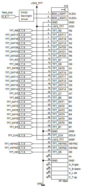
The display is connected via the 40 pin RGB 24 interface (X13). The touch lines for the touch controller are pinned separately via X5. The Display can be connected directly to the standard Kontron Display without need of an adapter.
The board is additionally equiped with an 50 pin RGB interface (X12). The touch controller pins are included. With this interface customer specific displays can be connected via a convenient display adapter (bonded on the display).
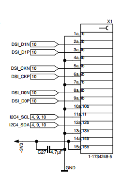
On X1 there is also a DSI interface.
Important
Only one interface (RGB or DSI) can be active at the same time.
Display backlight
Also see Using the hardware.
Display backlight is realized by Timer 4, channel 3. It is accessible thru linux
/sys/class/backlight/backlight/brightness interface.
RTC
Also see Using the hardware.
On this board the internal RTC is used.
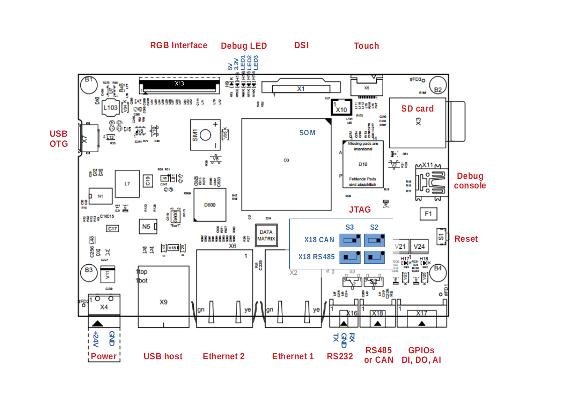
Appendix
Board Layout
Top view
Bottom view
Connector Pinouts
RS232, RS485, Speaker (X16, X18, X10)
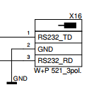
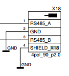
X16 uses the DTE configuration (TD is output, RD is input)
CAN configuration for X18 is RS485_A -> CAN_H, RS485_B -> CAN_L
CAN has an internal 120 ohms termination resistior
Touch, GPIO (X5, X17)
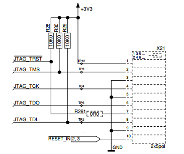
JTAG (X21)
Display (X1, X12, X13)
FAQ
My board doesn't boot any more
If your board doesn't boot any more check these things:
- Check if 5V and 3.3V led are lighten green. If none lights up, check your power supply. If only one lights up, your board is damaged!
- Check the boot switches. If LED1 flashes fast immediately after the power is switched on, it seems, that the device is in USB downloader mode. Either the boot switches are set to USB boot or the boot device doesn't contain a valid tf-a boot loader.
- Check your serial connection (115200 baud, 8bits, no parity)
- Try to boot from a fresh written SD card with bootable content